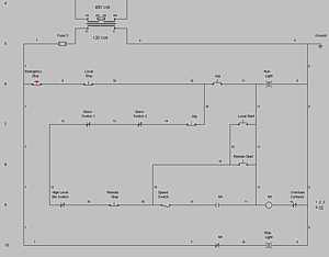
- #ELECTRICAL ONE LINE CIRCUIT DESIGN SOFTWARE DRIVER#
- #ELECTRICAL ONE LINE CIRCUIT DESIGN SOFTWARE SERIES#
This diagram clearly shows a 3 phase power generating station that transmits the power to the consumers below. The SLD diagram uses dedicated electrical symbols and icon for different components.Ī common example of a 3 phase power circuit to represent using a single line diagram would be the power transmission and distribution to the consumers. They are used for determining and isolating any faulty equipment in any power system during troubleshooting. it simplify complex 3 phase power circuits by showing all the electrical components and their interconnection. Single line diagram does not show the electrical connections of the component but it may show the size and ratings of the components being used. As the name suggests, a single line is used to denote the multiple power lines such as in 3 phase system.

Single Line diagram ( SLD) or one-line diagram is the representation of an electrical circuit using a single line.
#ELECTRICAL ONE LINE CIRCUIT DESIGN SOFTWARE SERIES#
It helps in showing the series and parallel connection between the components and the exact terminal connection between them. Unlike wiring diagram, it does not specify the real location of the components, the line between the components does not represent real distance between them. The schematic diagram of an electrical circuit shows the complete electrical connections between components using their symbols and lines.

It is pretty simple and easy to understand.

This diagram shows the process of converting an audio signal into frequency modulated signal.
#ELECTRICAL ONE LINE CIRCUIT DESIGN SOFTWARE DRIVER#
The following two examples of block diagram show an FM transmitter and a variable frequency driver VFD. This is why electricians do not rely on block diagram. It only represents the main components of the system and ignores any small components.

It lacks the information about the wiring and placement of individual components. It is the simplest form of electrical drawing as it only highlights the function of each component and provides the flow of process in the system.īlock diagram are easier to design and is the first stage in designing a complex circuit for any project. Single Line Diagram or One-line DiagramĪ block diagram is a type of electrical drawing that represents the principle components of a complex system in the form of blocks interconnected by lines that represent their relation.


 0 kommentar(er)
